
23JUL 2012
 © McGill School of Architecture
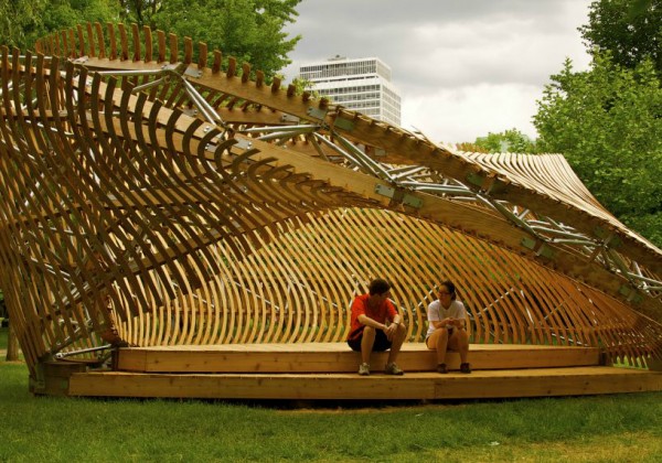
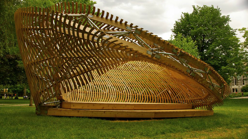
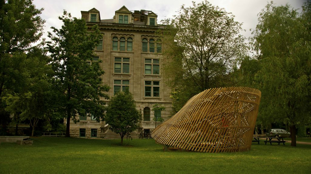
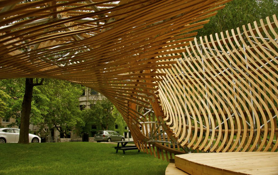
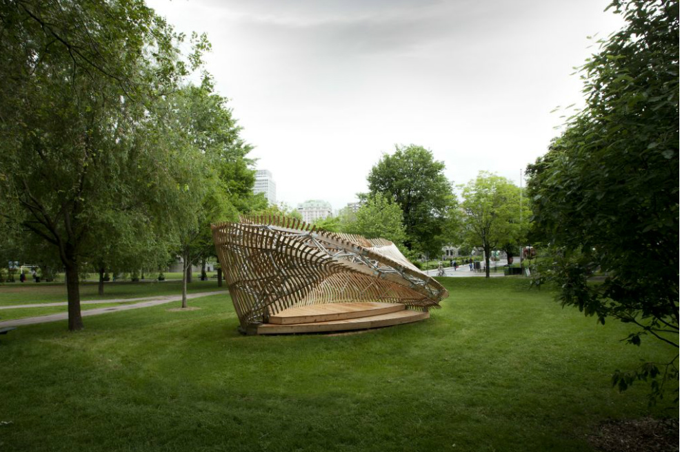
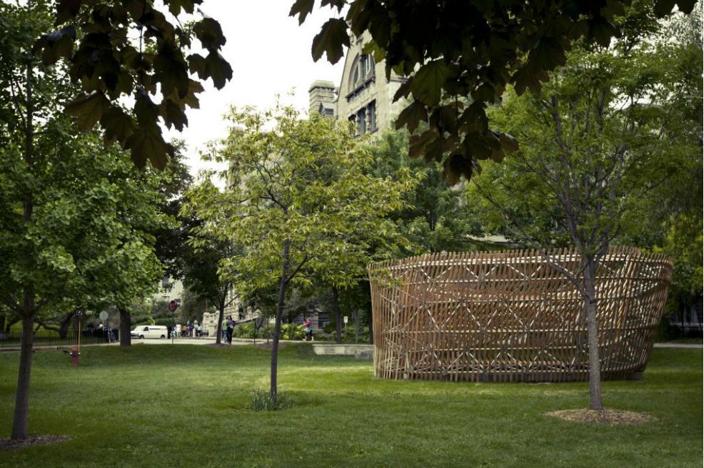
The pavilion occupies an 8.8m x 6.7m footprint with a total height of 3.7m in front of the Macdonald-Harrington building on the McGill University campus in Montreal, Quebec. The structure itself is comprised of 140 planar plywood ribs joined together with another 140 sheet metal node assemblies which are triangulated into a space frame by 266 metal tubes. The entire structure is clad with 302 moiré strips fixed to the ribs by 1208 trapezoidal plywood joints.
© McGill School of Architecture
The pavilion occupies an 8.8m x 6.7m footprint with a total height of 3.7m in front of the Macdonald-Harrington building on the McGill University campus in Montreal, Quebec. The structure itself is comprised of 140 planar plywood ribs joined together with another 140 sheet metal node assemblies which are triangulated into a space frame by 266 metal tubes. The entire structure is clad with 302 moiré strips fixed to the ribs by 1208 trapezoidal plywood joints.
 © McGill School of Architecture In total, there are 2056 discrete assemblies that comprise the pavilion and more than 3000 individually unique pieces of plywood, sheet metal and tubing.
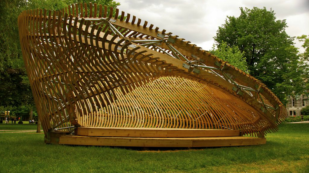
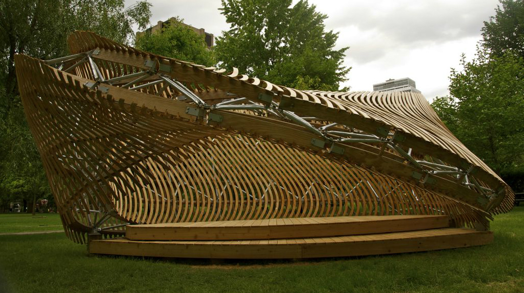
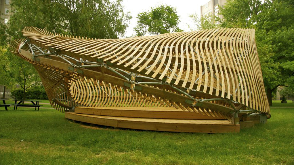
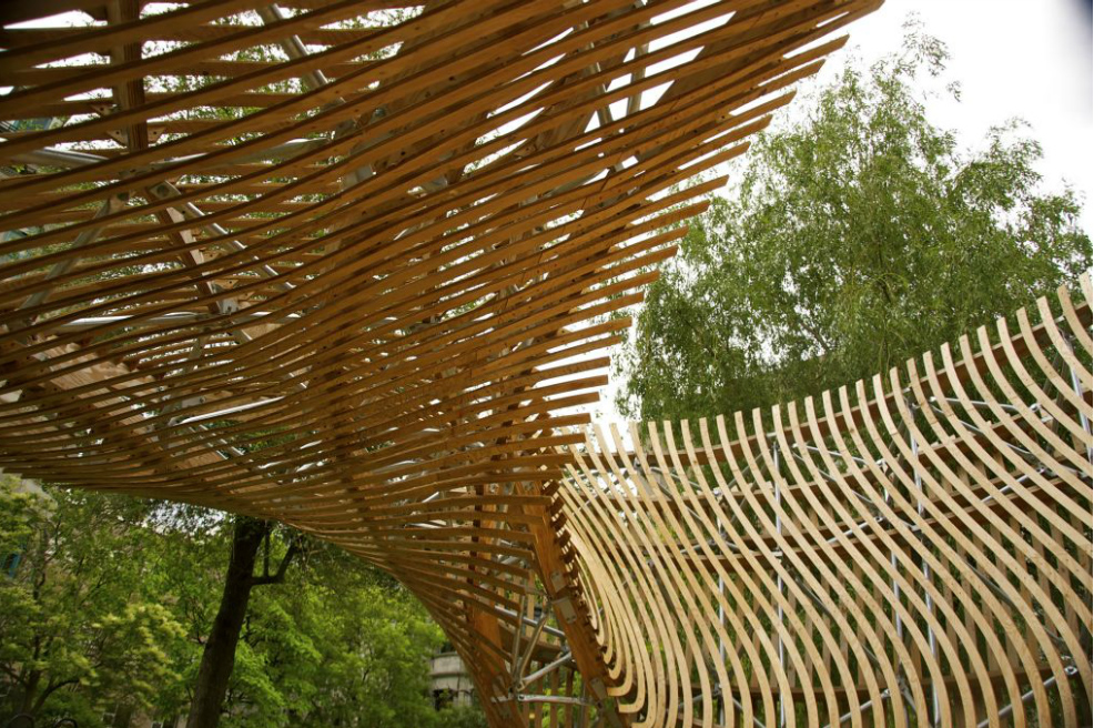
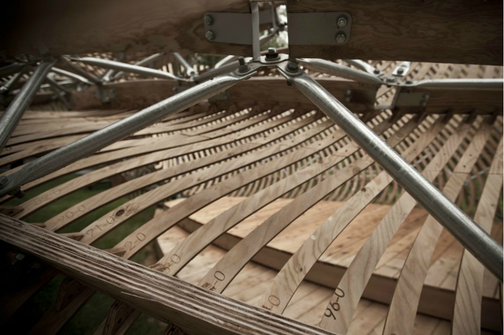
The pavilion’s hybrid lightweight space frame is formed by laminated plywood ribs and steel tubes clad with sinuous plywood strips. The complex structural system, in essence a space frame twisted around and attached to itself, provides a strong but flexible configuration that is capable of resolving the pavilion’s complex geometry without intruding upon the intended optical moiré effect. The effect is created by two apparent layers of cladding that define the volumetric envelope of the möbius strip. The laminated plywood ribs run along the möbius strip’s longitudinal isocurves, providing support for the moiré cladding elements, and are the main chords of the space frame.
© McGill School of Architecture In total, there are 2056 discrete assemblies that comprise the pavilion and more than 3000 individually unique pieces of plywood, sheet metal and tubing.
The pavilion’s hybrid lightweight space frame is formed by laminated plywood ribs and steel tubes clad with sinuous plywood strips. The complex structural system, in essence a space frame twisted around and attached to itself, provides a strong but flexible configuration that is capable of resolving the pavilion’s complex geometry without intruding upon the intended optical moiré effect. The effect is created by two apparent layers of cladding that define the volumetric envelope of the möbius strip. The laminated plywood ribs run along the möbius strip’s longitudinal isocurves, providing support for the moiré cladding elements, and are the main chords of the space frame.
 © McGill School of Architecture
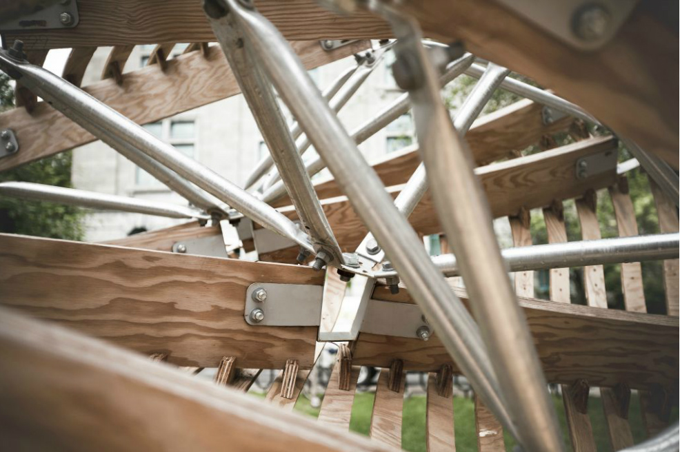
As primary structural members, these ribs experience both axial and bending forces. They are made of two layers of exterior grade BC fir plywood, laminated to a final thickness of 50mm. Transverse to the two surfaces of the möbius volume, a series of galvanised steel tubes with flattened ends form the bulk of the space frame structure. The ribs and tubes are connected to each other by two different types of steel plate joints. The first provides a pinned connection for the steel tubes.
© McGill School of Architecture
As primary structural members, these ribs experience both axial and bending forces. They are made of two layers of exterior grade BC fir plywood, laminated to a final thickness of 50mm. Transverse to the two surfaces of the möbius volume, a series of galvanised steel tubes with flattened ends form the bulk of the space frame structure. The ribs and tubes are connected to each other by two different types of steel plate joints. The first provides a pinned connection for the steel tubes.
 © McGill School of Architecture Pinned connection at all tube joints constrain them to work only under axial forces. The second connects the steel tubes to the plywood ribs, and the ribs to each other. Despite the compound angles of the incoming geometry, this joint also dealt with primarily axial forces.
Read less...
© McGill School of Architecture Pinned connection at all tube joints constrain them to work only under axial forces. The second connects the steel tubes to the plywood ribs, and the ribs to each other. Despite the compound angles of the incoming geometry, this joint also dealt with primarily axial forces.
Read less...
 © McGill School of Architecture
DEVELOPMENT
The complexity of the pavilion’s geometry creates a unique opportunity to undertake research through parametric modeling and digital fabrication. Parametric modeling consists of establishing a set of dynamic geometrical relationships to ultimately produce an entity with fixed dimensions. Its main advantage lies in rapid and flexible design exploration: designers can develop virtual prototypes, and simultaneously test the implications of changes on each of the multidisciplinary constraints shaping the project.
The selection of the möbius strip as a formal generator for the project necessitated a design, which would eventually require large numbers of similar yet unique components to resolve its continuously changing curvature. To deal with the formal complexity of the project, the team wrote a customized program in Grasshopper and vb.
© McGill School of Architecture
DEVELOPMENT
The complexity of the pavilion’s geometry creates a unique opportunity to undertake research through parametric modeling and digital fabrication. Parametric modeling consists of establishing a set of dynamic geometrical relationships to ultimately produce an entity with fixed dimensions. Its main advantage lies in rapid and flexible design exploration: designers can develop virtual prototypes, and simultaneously test the implications of changes on each of the multidisciplinary constraints shaping the project.
The selection of the möbius strip as a formal generator for the project necessitated a design, which would eventually require large numbers of similar yet unique components to resolve its continuously changing curvature. To deal with the formal complexity of the project, the team wrote a customized program in Grasshopper and vb.
 © McGill School of Architecturenet to generate design iterations, create concept proofs, and mock-ups. For example, this type of parametric modeling played a decisive role in the evaluation of the perceptual influence of the space frame structure on the intended optical effect of the cladding.
A driving principle in the design of the pavilion program was minimum static input and maximum dynamic derivation. Other than some numerical constants related to the real-world dimensions of construction materials, the program only required two simple geometric inputs: a digitally modeled möbius strip surface (representing the general shape and proportions) and a simple curve (used to derive the profiles of the cladding).
The mechanics of the program are complex but were conceived of as blocks of ideas, as in most commercial software. The first step is to define, from the input surface, a volume to contain structure.
© McGill School of Architecturenet to generate design iterations, create concept proofs, and mock-ups. For example, this type of parametric modeling played a decisive role in the evaluation of the perceptual influence of the space frame structure on the intended optical effect of the cladding.
A driving principle in the design of the pavilion program was minimum static input and maximum dynamic derivation. Other than some numerical constants related to the real-world dimensions of construction materials, the program only required two simple geometric inputs: a digitally modeled möbius strip surface (representing the general shape and proportions) and a simple curve (used to derive the profiles of the cladding).
The mechanics of the program are complex but were conceived of as blocks of ideas, as in most commercial software. The first step is to define, from the input surface, a volume to contain structure.
 © McGill School of Architecture The second step is to design the structural system, which will support the pavilion and provide a skeleton for the constantly curving surface of the cladding. The third step is to derive the profiles of the cladding elements and map them onto the curving surface. The final step is to resolve each connection point of structural and cladding elements into a geometry that can be fabricated.
In the first block of the program, the input möbius strip is subdivided to yield a dense cloud of points at a variable offset to form a möbius strip with a volume to contain the structural system. The offset incorporates a Gaussian function that smoothly adjusts the thickness to be lesser where the structure is cantilevered and greater where loads are transferred.
© McGill School of Architecture The second step is to design the structural system, which will support the pavilion and provide a skeleton for the constantly curving surface of the cladding. The third step is to derive the profiles of the cladding elements and map them onto the curving surface. The final step is to resolve each connection point of structural and cladding elements into a geometry that can be fabricated.
In the first block of the program, the input möbius strip is subdivided to yield a dense cloud of points at a variable offset to form a möbius strip with a volume to contain the structural system. The offset incorporates a Gaussian function that smoothly adjusts the thickness to be lesser where the structure is cantilevered and greater where loads are transferred.
 © McGill School of Architecture Similar offsets from the original möbius strip define wooden structural ribs and the surface upon which the exterior cladding profiles are mapped.
In the second block of the program, the primary surface is used to generate a set of ideal nodes that represent junction points of the space frame elements. The number of nodes can be varied in both the uand v-directions. These variables offer possibilities for optimizing structural performance and fabrication cost. The process of translating the ideal nodes into real nodes is complex as a result of the necessity of using a 3-axis CNC router to fabricate all wooden members to be used in the project. This constraint was turned into a design opportunity.
© McGill School of Architecture Similar offsets from the original möbius strip define wooden structural ribs and the surface upon which the exterior cladding profiles are mapped.
In the second block of the program, the primary surface is used to generate a set of ideal nodes that represent junction points of the space frame elements. The number of nodes can be varied in both the uand v-directions. These variables offer possibilities for optimizing structural performance and fabrication cost. The process of translating the ideal nodes into real nodes is complex as a result of the necessity of using a 3-axis CNC router to fabricate all wooden members to be used in the project. This constraint was turned into a design opportunity.
 © McGill School of Architecture The junctions were treated as ring joints. In this way, the intersection point of the incoming loads became empty space. These joints became complex as a result of the disparate planes of the adjacent wooden ribs and the necessary coplanarity of the flattened ends of the space frame tubes. As a result the metal joints of the program’s automated optimization of the joints, they could be fabricated efficiently from laser cut steel sheet metal subsequently CNC bent into the proper shape. Unfortunately, certain areas of high curvature in the form of the pavilion yielded a node network with such acute geometry that structural members physically overlapped.
 © McGill School of Architecture This proved to be a problem that no simple geometrical solutions would solve as a particular joint’s geometry and that of the adjacent joints are interdependent. Several design iterations and much research was required before a recursive relaxation algorithm was developed. This algorithm seeks a balance between joint size and deviation from the angles defined by the idealized node network. Once the overall geometric parameters have been defined, the program proceeds with the more basic but lengthy geometric manipulations to generate the real components to be fabricated using sheet metal.
The third block of the program generated the cladding profiles and mapped them onto the möbius volume.
© McGill School of Architecture This proved to be a problem that no simple geometrical solutions would solve as a particular joint’s geometry and that of the adjacent joints are interdependent. Several design iterations and much research was required before a recursive relaxation algorithm was developed. This algorithm seeks a balance between joint size and deviation from the angles defined by the idealized node network. Once the overall geometric parameters have been defined, the program proceeds with the more basic but lengthy geometric manipulations to generate the real components to be fabricated using sheet metal.
The third block of the program generated the cladding profiles and mapped them onto the möbius volume.
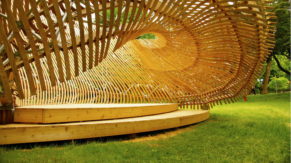
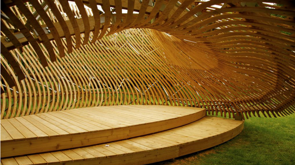
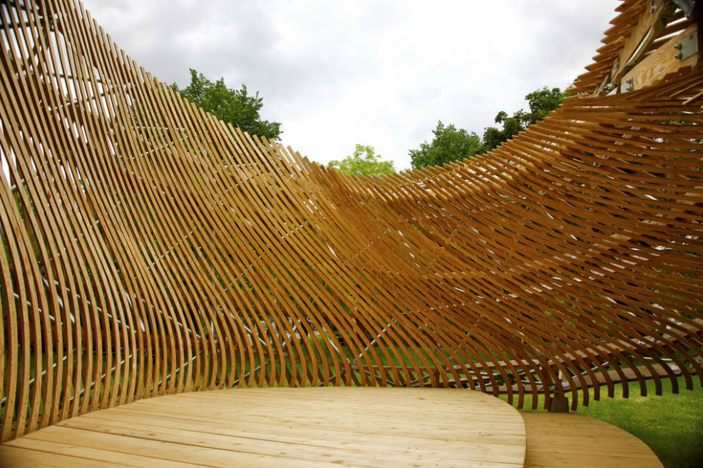
 © McGill School of Architecture The design intention for the cladding profiles, besides creating the moiré interference pattern, was to hint at the continuity of the pavilion’s surface. The profiles sequentially morph from a straight line to one that is significantly curved, then back to straight. Close inspection of the “wall” segment of the pavilion shows how double möbius geometry is exploited to juxtapose the straightest profiles on one side with the most curved on the other. To accomplish this feature, the program first creates a cylinder and a circular array of intermediary curves that transition between a straight line and the maximum curvature profile -the second static input to the code. The cylinder is the preliminary surface of choice because it is topologically equivalent to a double möbius surface. The number of intermediary curves is variable and is adjusted to maximize the interference effect.
 © McGill School of Architecture Projection of the derived curves onto the cylinder establishes u- and vcoordinates that are mapped onto the möbius surface. The final step in defining the cladding strips is to give each of them width by extruding a variable-diameter pipe along the length of the mapped moiré curves. Each pipe profile is then intersected with the möbius surface to yield a surface cladding that subtly tapers to ensure adequate distance between neighbors where the pavilion’s form is highly curved. The fourth and final block of the program deals with the geometrical challenge of connecting the two independently derived elements -the structural subframe and the cladding. A resulting joint detail affixes the moiré cladding to the edge of the plywood ribs with a trapezoidal piece of plywood that takes into account the pitch of the rib relative the each cladding strip, and the centerline of the cladding at that point.
 © McGill School of Architecture Connecting the planar wood cladding to more than one trapezoidal joint induces curvature. As a result these trapezoidal joints create a smooth double-curved surface from planar components. Because of the limitations of the available 3-axis machine to fabricate these parts, a two-step milling process was required. First the profile and precise registration holes were milled. Afterwards, a notch at an angle not perpendicular to the plane of the joint itself was cut to account for the variable compound angles of the structure at the joint intersection.
FABRICATION
The transfer of the design information from the parametric model to the fabricators was facilitated by programs such as Rhinoceros 3D, RhinoNest, RhinoCAM, and Solidworks.
© McGill School of Architecture Connecting the planar wood cladding to more than one trapezoidal joint induces curvature. As a result these trapezoidal joints create a smooth double-curved surface from planar components. Because of the limitations of the available 3-axis machine to fabricate these parts, a two-step milling process was required. First the profile and precise registration holes were milled. Afterwards, a notch at an angle not perpendicular to the plane of the joint itself was cut to account for the variable compound angles of the structure at the joint intersection.
FABRICATION
The transfer of the design information from the parametric model to the fabricators was facilitated by programs such as Rhinoceros 3D, RhinoNest, RhinoCAM, and Solidworks.
 © McGill School of Architecture The variability in length of the steel bars, the size and shape of the moiré strips and other wooden elements of the structure, and the specific bending angles in the steel joints are all factors requiring the use of automated processes and computational fabrication. The adaptability of the model and the digital fabrication tools employed permitted the fine-tuning of all architectural details, bringing the virtual model closer to the final built artifact, despite its geometrical complexity.
The plywood ribs and moiré strips were cut using a 3-axis CNC router, shared by School of Architecture and Faculty of Engineering. Nearly one hundred sheets of plywood were consumed to produce all of the components fabricated in-house. Most of the wood components were designed as planar pieces, thus their perimeters served as tool paths in the cutting process.
© McGill School of Architecture The variability in length of the steel bars, the size and shape of the moiré strips and other wooden elements of the structure, and the specific bending angles in the steel joints are all factors requiring the use of automated processes and computational fabrication. The adaptability of the model and the digital fabrication tools employed permitted the fine-tuning of all architectural details, bringing the virtual model closer to the final built artifact, despite its geometrical complexity.
The plywood ribs and moiré strips were cut using a 3-axis CNC router, shared by School of Architecture and Faculty of Engineering. Nearly one hundred sheets of plywood were consumed to produce all of the components fabricated in-house. Most of the wood components were designed as planar pieces, thus their perimeters served as tool paths in the cutting process.
 © McGill School of Architecture However, the curving moiré strips required a final operation within the program before their 2D tool paths could be determined. Since the moiré surfaces were roughly aligned with the transverse isocurves of the möbius strip, they were extremely close to being singly-curved, “developable” surfaces. A fairly simple flattening algorithm was used that gave flattened outlines with minimal distortion.
In order to minimize material waste, the nesting program RhinoNest was used to efficiently place and reorient the great number of subtly differing cutting tool paths onto the sheet stock. In order to keep track of the thousands of parts, each required a unique label indicating its mate in assembly and its location within the pavilion. A hierarchical identification system transmits the data structure of the program onto the real world parts in order to facilitate on-site assembly without the use of drawings.
© McGill School of Architecture However, the curving moiré strips required a final operation within the program before their 2D tool paths could be determined. Since the moiré surfaces were roughly aligned with the transverse isocurves of the möbius strip, they were extremely close to being singly-curved, “developable” surfaces. A fairly simple flattening algorithm was used that gave flattened outlines with minimal distortion.
In order to minimize material waste, the nesting program RhinoNest was used to efficiently place and reorient the great number of subtly differing cutting tool paths onto the sheet stock. In order to keep track of the thousands of parts, each required a unique label indicating its mate in assembly and its location within the pavilion. A hierarchical identification system transmits the data structure of the program onto the real world parts in order to facilitate on-site assembly without the use of drawings.
 © McGill School of Architecture The code generates a set of line drawings that mapped the path the CNC router would take to both cut the contour of the piece, engrave labels, drill registration holes and mill joinery for assembly.
The steel joints were manufactured by a local prototype fabricator with CNC bending capabilities. The precision of this process was necessary to bridge between the continuous doubly-curved geometry of the overall möbius shape and the planar components. One of the major difficulties arising as result, were the numerous compound angles that the joints had to accommodate. Accurate measuring of these angles manually proved to be enormously difficult, but could easily be described digitally.
© McGill School of Architecture The code generates a set of line drawings that mapped the path the CNC router would take to both cut the contour of the piece, engrave labels, drill registration holes and mill joinery for assembly.
The steel joints were manufactured by a local prototype fabricator with CNC bending capabilities. The precision of this process was necessary to bridge between the continuous doubly-curved geometry of the overall möbius shape and the planar components. One of the major difficulties arising as result, were the numerous compound angles that the joints had to accommodate. Accurate measuring of these angles manually proved to be enormously difficult, but could easily be described digitally.
 © McGill School of Architecture In order to fabricate this geometry, the part was unfolded into the flat pattern of a sheet metal object, in a process similar to the one used to unroll the moiré strips. This is analogous to the flat cardboard pattern of a box before it is folded into a cube. The unfolding of the part took into account the radius of bending of the sheet metal, based on its thickness and modulus. A line was etched onto the flat sheet metal to indicate where the bend was to be made, and the operator of the CNC bender only had to align this indicator and prompt the machine to bend it to the angle designated by the computer program.
Digital fabrication of the ribs, moiré and the steel joints permitted the assembly of an irregular space frame that could adapt to the variable curvature of the surface.
© McGill School of Architecture In order to fabricate this geometry, the part was unfolded into the flat pattern of a sheet metal object, in a process similar to the one used to unroll the moiré strips. This is analogous to the flat cardboard pattern of a box before it is folded into a cube. The unfolding of the part took into account the radius of bending of the sheet metal, based on its thickness and modulus. A line was etched onto the flat sheet metal to indicate where the bend was to be made, and the operator of the CNC bender only had to align this indicator and prompt the machine to bend it to the angle designated by the computer program.
Digital fabrication of the ribs, moiré and the steel joints permitted the assembly of an irregular space frame that could adapt to the variable curvature of the surface.
 © McGill School of Architecture This shape would not allow for the mass production of similar parts but required 2175 unique components to generate its structure and cladding. Despite each piece being fabricable by more conventional technology, it was the variability and precision of the digital fabrication process that allowed us to produce so many components which, despite some minor deviation from the digital model during assembly, still fit together within their tolerances to yield the form we sought to build.
EFFECT
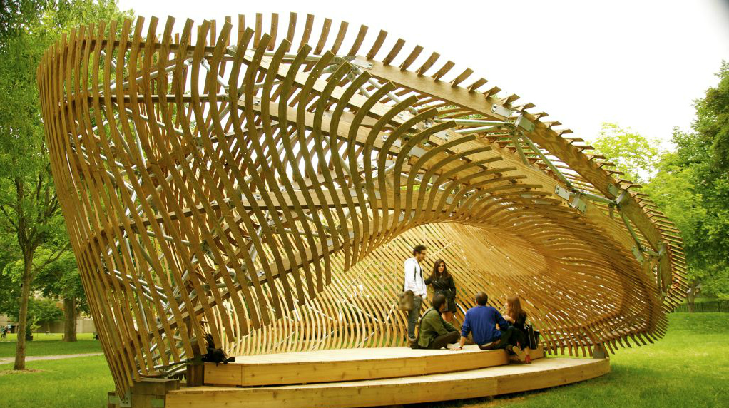
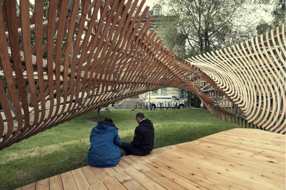
The pavilion sits, in a number of uneasy ways, between states. Its overall form is that of a möbius strip, a continuous, non-orientable surface, which confounds interiority and exteriority. The cladding and structure reinforce the state of uncertainty induced by the möbius geometry. As the object is approached, the visual field is interrupted by movement-induced interference and the viewer becomes aware of an optical fluctuation of the surface of the pavilion via the moiré effect.
© McGill School of Architecture This shape would not allow for the mass production of similar parts but required 2175 unique components to generate its structure and cladding. Despite each piece being fabricable by more conventional technology, it was the variability and precision of the digital fabrication process that allowed us to produce so many components which, despite some minor deviation from the digital model during assembly, still fit together within their tolerances to yield the form we sought to build.
EFFECT
The pavilion sits, in a number of uneasy ways, between states. Its overall form is that of a möbius strip, a continuous, non-orientable surface, which confounds interiority and exteriority. The cladding and structure reinforce the state of uncertainty induced by the möbius geometry. As the object is approached, the visual field is interrupted by movement-induced interference and the viewer becomes aware of an optical fluctuation of the surface of the pavilion via the moiré effect.
 © McGill School of Architecture Perception oscillates between the form of the continuous möbius surface to the shifting pattern of the cladding. Light filters through the cladding, reinforcing the ambiguity of the place. The möbius itself vacillates between an appearance of relative volumetric solidity and a doubled set of surfaces. It is within this unstable appearance that a new place to sit, relax and think is provided literally outside of the otherwise more stressful academic environment of the contemporary classroom.
A revolution in digital modeling tools has enabled a new generation of designers to model anything that they are capable of imagining.
© McGill School of Architecture Perception oscillates between the form of the continuous möbius surface to the shifting pattern of the cladding. Light filters through the cladding, reinforcing the ambiguity of the place. The möbius itself vacillates between an appearance of relative volumetric solidity and a doubled set of surfaces. It is within this unstable appearance that a new place to sit, relax and think is provided literally outside of the otherwise more stressful academic environment of the contemporary classroom.
A revolution in digital modeling tools has enabled a new generation of designers to model anything that they are capable of imagining.
 © McGill School of Architecture A typical problem with many of the resulting designs is that it is very difficult to move past the formal superficiality of the digital model into confronting the physical limitations and complications of construction. The production of the ContemPLAY pavilion engaged the question of learning not through the representation of potential project but in questioning through making. In this way, formal possibility and technical complexity were interrogated by fabrication. As a designbuild effort, the project team confronted research into cutting-edge processes within the many challenges of bringing any design to reality.
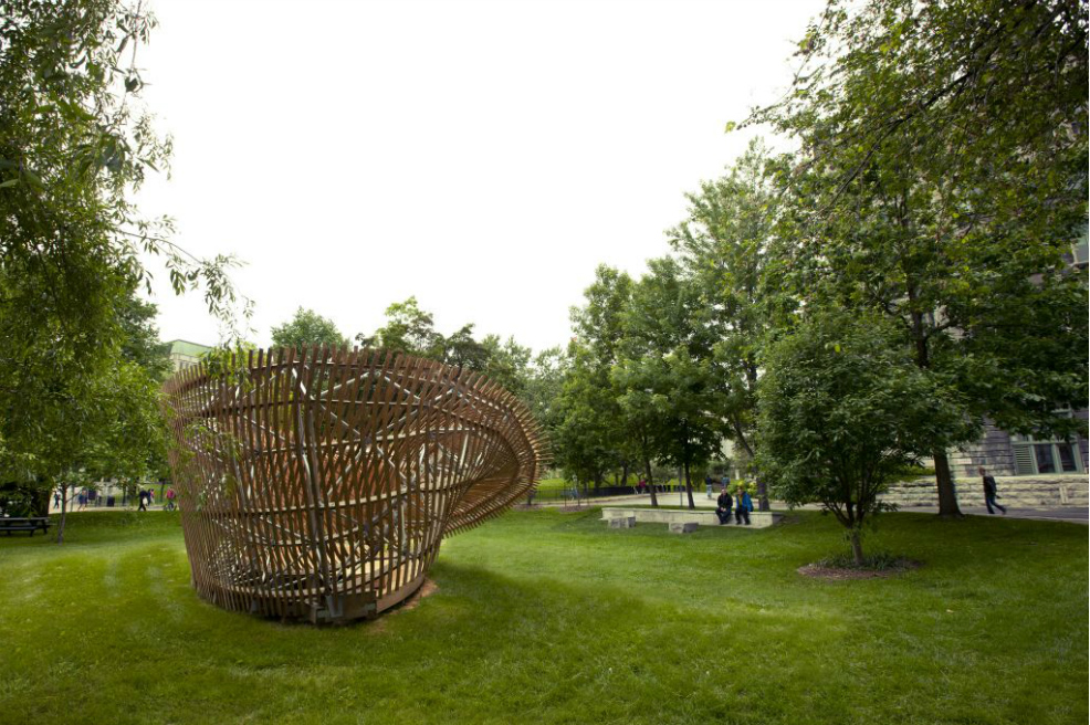
The ContemPLAY pavilion project began as an exercise in parametric design and digital fabrication, and the built form now exists as an architectural statement about resolving complexity. The pavilion is a device for provoking inquiry, thoughtfulness, and even wonder about spaces and objects in one’s environment.
© McGill School of Architecture A typical problem with many of the resulting designs is that it is very difficult to move past the formal superficiality of the digital model into confronting the physical limitations and complications of construction. The production of the ContemPLAY pavilion engaged the question of learning not through the representation of potential project but in questioning through making. In this way, formal possibility and technical complexity were interrogated by fabrication. As a designbuild effort, the project team confronted research into cutting-edge processes within the many challenges of bringing any design to reality.
The ContemPLAY pavilion project began as an exercise in parametric design and digital fabrication, and the built form now exists as an architectural statement about resolving complexity. The pavilion is a device for provoking inquiry, thoughtfulness, and even wonder about spaces and objects in one’s environment.
It manipulates viewers’ perceptions through its overall form and carefully arrayed details, inviting the user to discern the boundaries between public furniture, shelter, and art..
 © McGill School of Architecture
 © McGill School of Architecture
 © McGill School of Architecture
 © McGill School of Architecture
 © McGill School of Architecture
 © McGill School of Architecture
 © McGill School of Architecture
 © McGill School of Architecture
 © McGill School of Architecture
 © McGill School of Architecture
 © McGill School of Architecture
 © McGill School of Architecture
 © McGill School of Architecture
 © McGill School of Architecture
 © McGill School of Architecture
 © McGill School of Architecture
 © McGill School of Architecture
 © McGill School of Architecture
 © McGill School of Architecture
 © McGill School of Architecture
 on Vimeo - ©
contemPLAY pavilion / McGill School of Architecture
Posted in Architecture - Pavilion by FORMAKERS | Tags: Parametric
The ContemPLAY pavilion project is a student-led initiative investigating new methods of practice. The project presented a unique opportunity for the students of the Directed Research Studio (DRS) of the McGill School of Architecture to learn through hands-on experience in an academic context. DRS masters students in coordination with the Facility for Architectural Research in Media and Mediation (FARMM) are responsible for the design, fabrication and assembly of the parametric pavilion.© McGill School of Architecture© McGill School of Architecture© McGill School of Architecture© McGill School of Architecture© McGill School of Architecture© McGill School of Architecture© McGill School of Architecture© McGill School of Architecture© McGill School of Architecture© McGill School of Architecture© McGill School of Architecture© McGill School of Architecture© McGill School of Architecture© McGill School of Architecture© McGill School of Architecture© McGill School of Architecture© McGill School of Architecture© McGill School of Architecture© McGill School of Architecture© McGill School of Architecture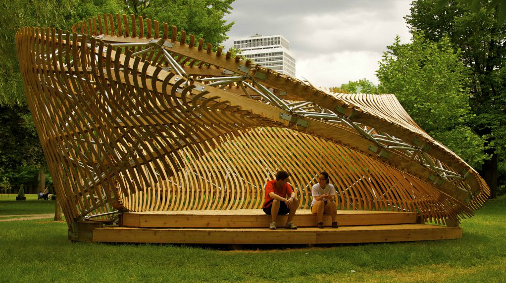 © McGill School of Architecture
 © McGill School of Architecture
 © McGill School of Architecture
 © McGill School of Architecture
 © McGill School of Architecture
 © McGill School of Architecture
 © McGill School of Architecture
 © McGill School of Architecture
 © McGill School of Architecture
 © McGill School of Architecture
 © McGill School of Architecture
 © McGill School of Architecture
 © McGill School of Architecture
 © McGill School of Architecture
 © McGill School of Architecture
 © McGill School of Architecture
 © McGill School of Architecture
 © McGill School of Architecture
 © McGill School of Architecture
 © McGill School of Architecture
on Vimeo - ©
© McGill School of Architecture
on Vimeo - ©
Comments
No comments
Sign in »